Systems & Hardware
Proximity-Activated Candy Dispenser
Katie Lee and I built this for Princeton's ECE203: a hand-proximity-triggered candy dispenser that watches for a hand with an IR sensor, holds its own cooldown on an analog timer, and dispenses through a servo swing. The build is simple. The debugging wasn't.
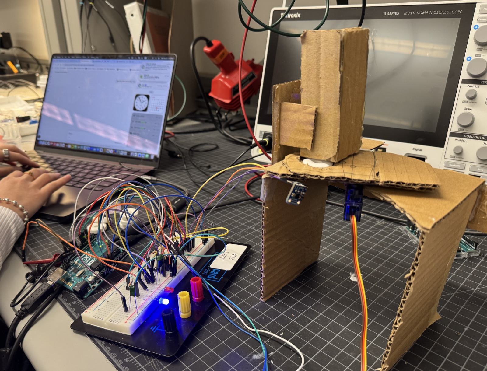
Five parts share one 5V rail: a VCNL4010 proximity sensor, an Arduino Uno running the decision logic, an NE555 timer holding a hardware cooldown so a lingering hand can't re-trigger mid-cycle, a servo swinging 0° to 90° and back to dispense, and two LEDs, red mid-cycle and blue at reset, that report system state without anyone needing to open the Serial Monitor.
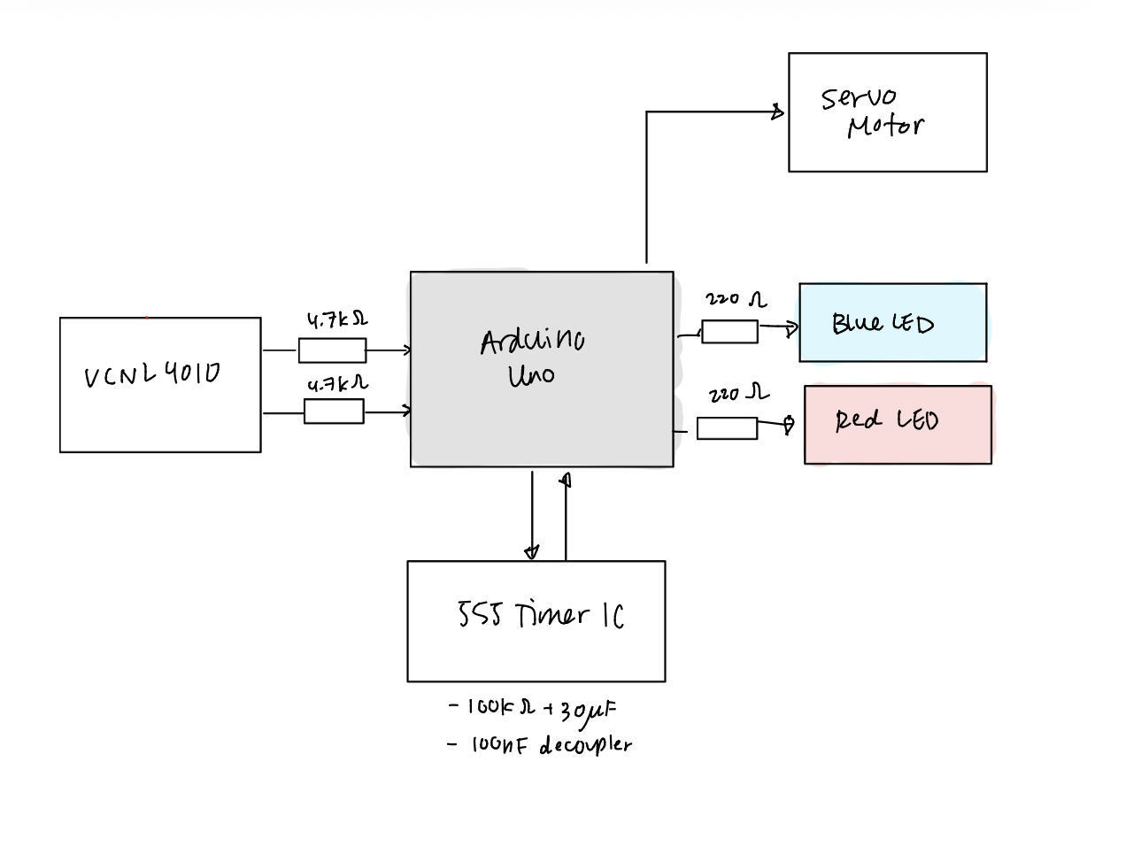
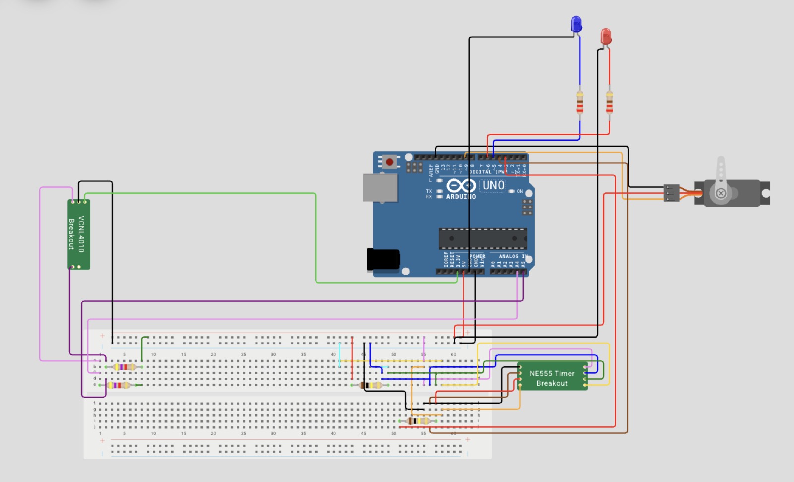
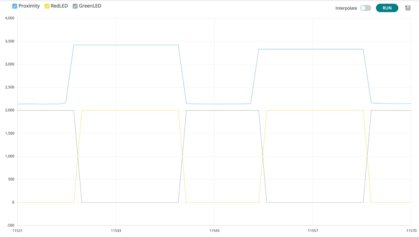
First fault was the sensor: a flat, unchanging proximity reading no matter how close a hand got, even though the Arduino still recognized it on the bus. Our first suspicion was a short from soldering. What we'd actually left out was pull-up resistors: without 4.7kΩ pull-ups on SDA and SCL, the Arduino couldn't resolve a clean high from a clean low on the I²C lines, so the readings never moved. Adding them turned a dead trace into a sensor that held a stable ~2,180 counts at rest and spiked past 3,000 the moment a hand came into range, comfortably clear of the ~2,800–3,000 threshold we settled on.
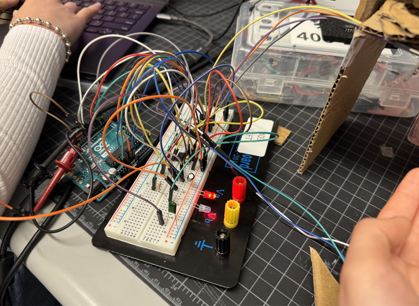
Second fault was the 555 timer, and it took longer to pin down because it wasn't consistent. Some cycles the ~3.3-second cooldown, T = 1.1 × 100kΩ × 30μF, ran and reset cleanly; other times the timer output latched high and never returned, locking the system out of its own reset. We went through it point by point with a multimeter, at different points suspecting a dead capacitor and a floating trigger pin. Both turned out to be real: swapping the capacitor and adding a 10kΩ pull-up to the trigger pin fixed it.
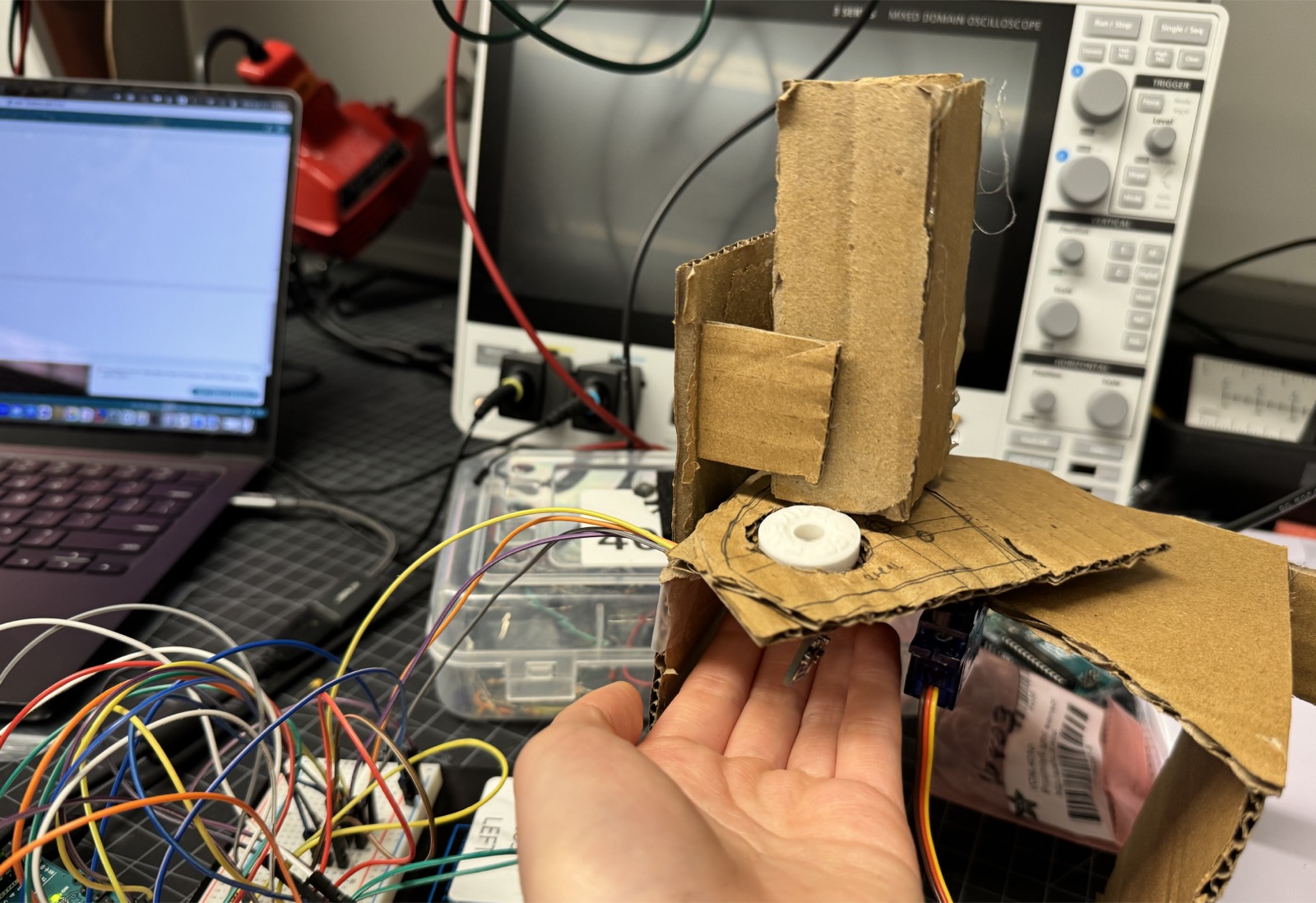
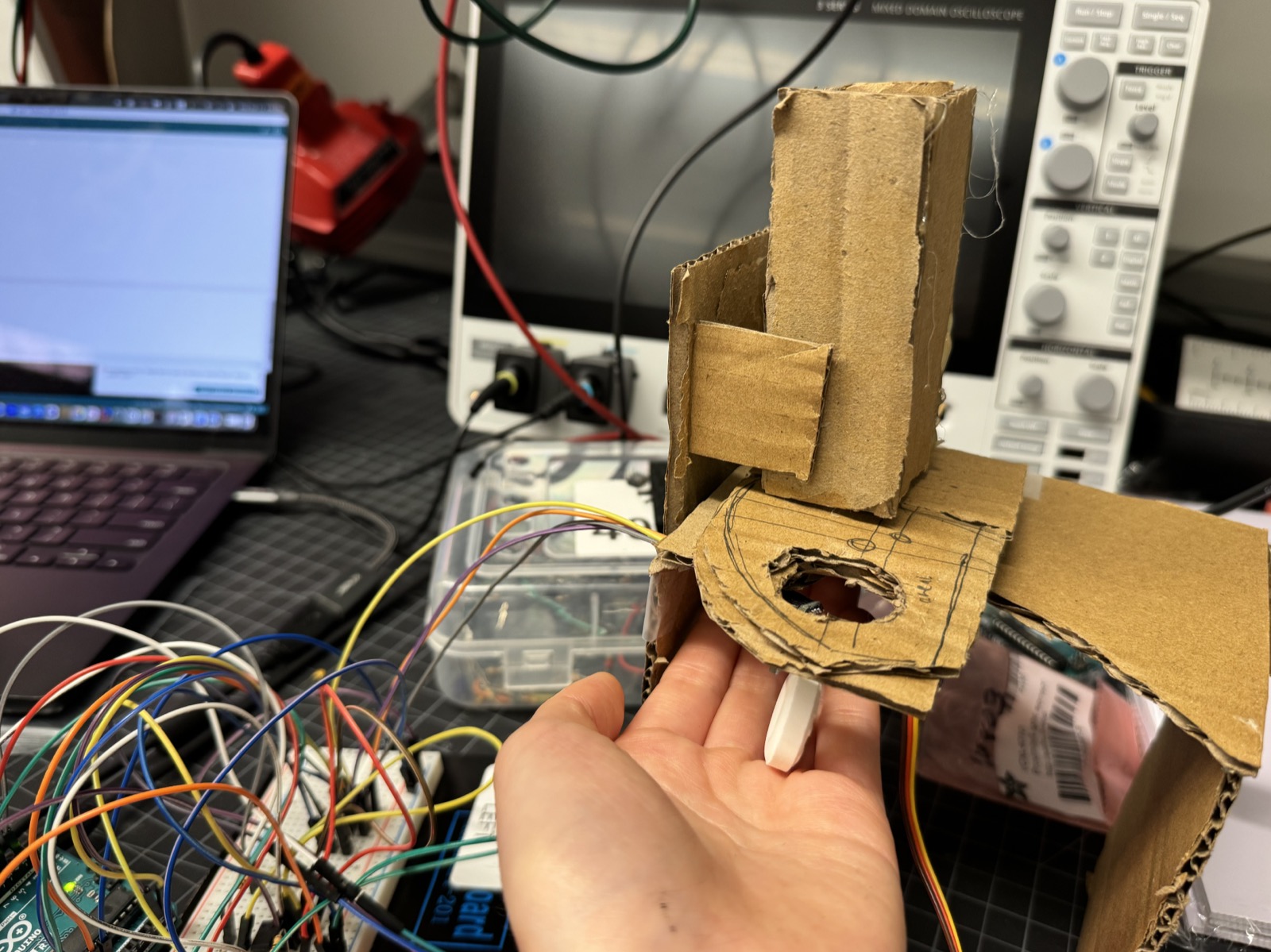
Neither fault announced which layer it lived in. A sensor reading nothing could be a bad connection, a bad component, or a bad protocol configuration, and only one of those was true here; a timer that runs correctly most of the time looks like intermittent bad luck until you've ruled out the capacitor and the floating pin separately. What actually worked was checking each layer in isolation before touching the code: retrace the physical wiring, cross-check it against expected circuit behavior, and only then look at logic.
Given more time, the LEDs would wire directly to the 555 output instead of routing through the Arduino, making the feedback fully hardware-driven and independent of software state. The fixed timing resistor would become a potentiometer so the cooldown is tunable without reflashing. And the cardboard chassis, right for a prototype built against a deadline, would become an enclosure that shields the sensor from ambient light instead of one taped together from whatever was on the bench.
Arduino sketch
#include <Wire.h>
#include <Servo.h>
#include "Adafruit_VCNL4010.h"

Adafruit_VCNL4010 vcnl;
Servo myServo;

const int SERVO_PIN = 9;
const int LED_BLUE_PIN = 5;
const int LED_RED_PIN = 6;
const int TIMER_OUT_PIN = 3;
const int TIMER_IN_PIN = 4;

const uint16_t PROX_THRESHOLD = 3000;
const int      SERVO_OPEN_DEG = 90;
const int      SERVO_CLOSE_DEG = 0;
const int      DISPENSE_MS = 600;

bool inCooldown = false;

void setup() {
  Serial.begin(9600);
  delay(1000);

  Wire.begin();
  Wire.setClock(100000);

  pinMode(LED_BLUE_PIN, OUTPUT);
  pinMode(LED_RED_PIN, OUTPUT);
  pinMode(TIMER_OUT_PIN, OUTPUT);
  pinMode(TIMER_IN_PIN, INPUT);
  digitalWrite(TIMER_OUT_PIN, LOW);

  myServo.attach(SERVO_PIN);
  myServo.write(SERVO_CLOSE_DEG);

  if (!vcnl.begin()) {
    while (1) {
      digitalWrite(LED_BLUE_PIN, HIGH);
      digitalWrite(LED_RED_PIN, LOW);
      delay(300);
      digitalWrite(LED_BLUE_PIN, LOW);
      digitalWrite(LED_RED_PIN, HIGH);
      delay(300);
    }
  }

  digitalWrite(LED_BLUE_PIN, HIGH);
  digitalWrite(LED_RED_PIN, LOW);
}

void sweepTo(int targetDeg) {
  myServo.write(targetDeg);
  delay(100);
}

void dispense() {
  inCooldown = true;

  digitalWrite(LED_BLUE_PIN, LOW);
  digitalWrite(LED_RED_PIN, HIGH);

  digitalWrite(TIMER_OUT_PIN, HIGH);
  delay(10);
  digitalWrite(TIMER_OUT_PIN, LOW);

  sweepTo(SERVO_OPEN_DEG);
  delay(DISPENSE_MS);
  sweepTo(SERVO_CLOSE_DEG);

  while (inCooldown && digitalRead(TIMER_IN_PIN) == HIGH) {
    delay(50);
  }

  inCooldown = false;
  digitalWrite(LED_RED_PIN, LOW);
  digitalWrite(LED_BLUE_PIN, HIGH);
}

void loop() {
  if (!inCooldown && vcnl.readProximity() > PROX_THRESHOLD) {
    dispense();
  }

  delay(50);
}